Insulators of the Battleford Telegraph Line
By Robin Plewes
It’s been a long time since I have been able to sit down and gather some thoughts for a Canadian Forum column. With a foot of snow on the ground here in Ontario, outside tasks have been put on hold till spring.
While puttering with insulators I came across the stash of Baby Battleford threadless shards, formally of Ren Settle, who after many weeks of research and hiking unearthed an early telegraph depot in northern Saskatchewan {CJ Sept 1972}. This depot would have been part of the Dominion Telegraph network being constructed in the late 1880s.
The discovery was written up in both Crown Jewels and Canadian Forum Magazine. These articles detailed the discovery but there were not a lot of details on the actual insulators themselves. As there are many shards to examine, I thought it would be a good opportunity to look them over and perhaps document the characteristics, as others may not have seen such a line up previously.
As the insulator is most commonly found in olive blackglass, many collectors interested in either threadless or Canadian insulators would have an example in their collection and leave it at that. The aqua colored glass examples are hard to find and the listing for a light green color is a very rare insulator.
A few have been reportedly found in southern Ontario, but most originate from western Canada. With many being dark olive colors, it is reasonable to assume they would date to the 1870s – 1880s time frame when glass houses were working with simple formulas and limited materials. As glass quality improved, perhaps the aqua examples were the last ones made. Alternatively, the aqua insulators may have been made at a different location as their molds are distinct from the molds of the dark olive examples. The few aqua glass pieces I have are of reasonable quality, where-as some of the dark olive examples have impurities, fine bubbles and wrinkles in the glass.
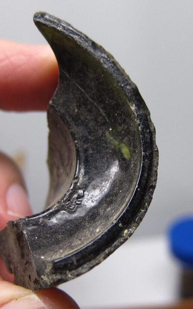
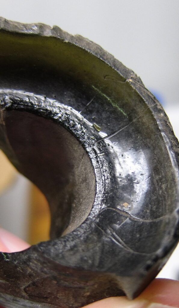
As my observations have been made via boxes of shards, there are many examples to consider, but few complete insulators to photograph. Unfortunately some features can only be shown here through the pieces at hand.
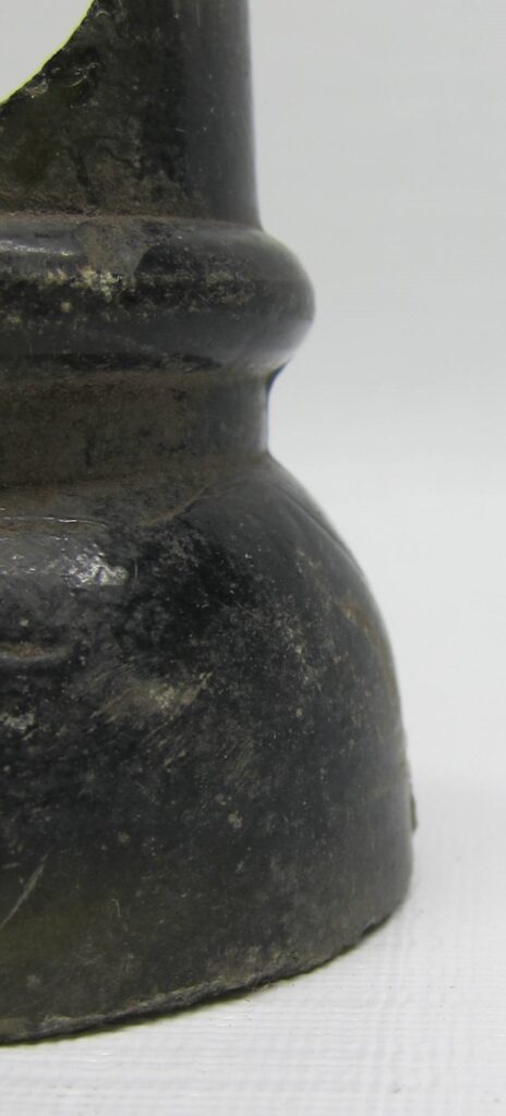
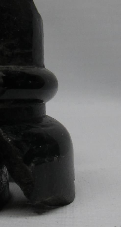
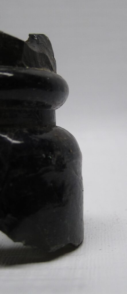
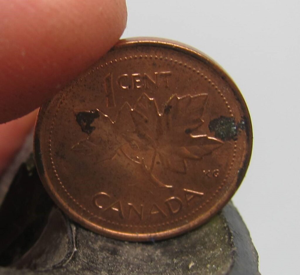
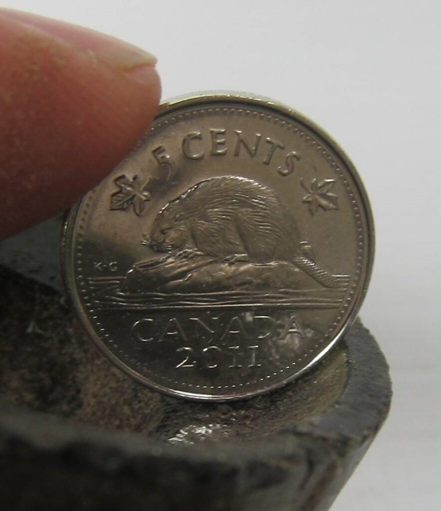
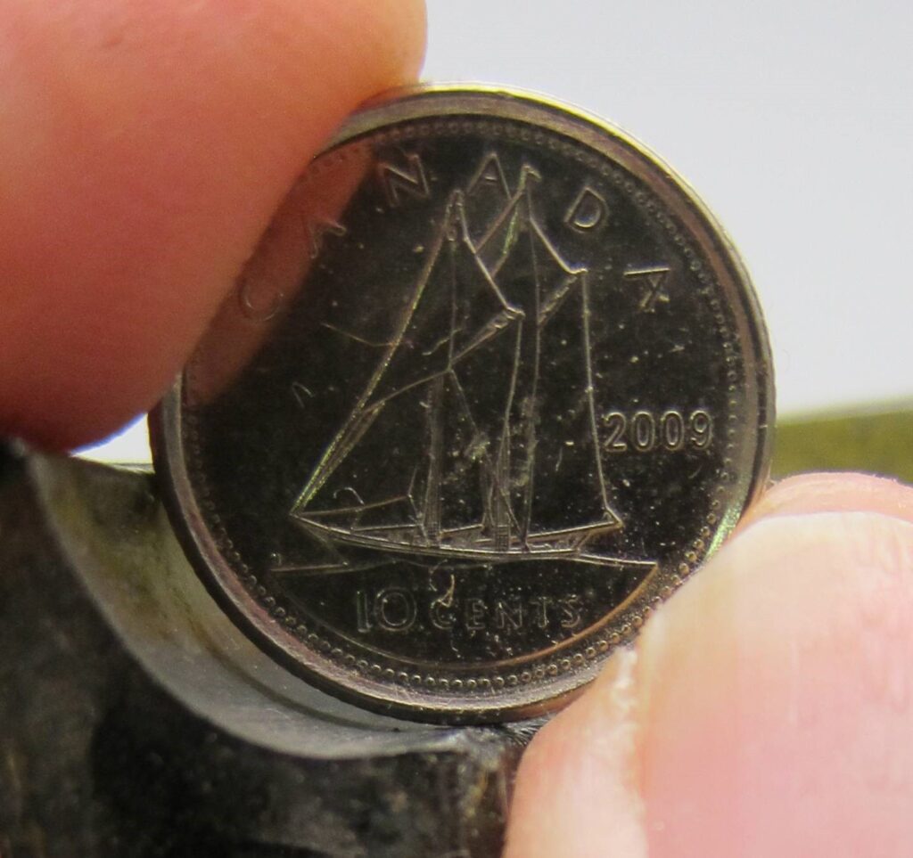
As seen in the 3 pictures above, there seems to be 3 wire groove/skirt styles for dark olive insulators. By looking at the lower edge of the wire groove, there are 3 different angles to the start of the skirt. It is also interesting that I found 3 different inner curvatures to the outer edge of the base. {Details later on}
While I do not have any aqua examples to study, I can see from various pictures that the molds for the aqua insulators are not the same as the dark olive ones. The aqua glass examples have a noticeably wider wire grove when compared to the dark olive insulators.
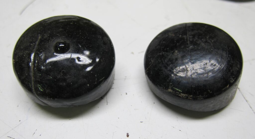
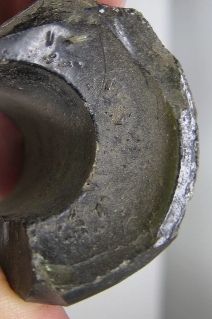
In summary of the mold count, there are 2 for the aqua insulators {one has a bump in the center of the crown and one does not} and at least 4 for the dark olive insulators. The square shouldered style comes with a bump in the center of the crown. An example of this bump can be seen in the picture to the right.
As I sorted through the pieces, I noticed a few features that got me thinking about how these little insulators had been made. With dozens of domes to compare, the amount of domeglass {as collectors know the thickness of glass above the pinhole} is commonly between .35” and .55”.
All examples have the lower end of the pin hole starting about .400″ up from the base of the insulator. Most bases of 734.8 insulators were easily chipped up to some degree {more on that below}. The .400″ measurement was only taken from sections where the original base could be determined.
The dome height above the wire groove ridge is also consistent at about 1.10”.
With all of the above dimensions being fairly consistent, the variation due to the amount of glass in any given insulator pressing is seen in the height of the skirt. The skirt height from the base to the bottom of the wire groove can vary between .75” and 1.25”. Put another way, if we were to look at a cross section of this insulator style, this variation can be seen in the length of the pin hole below the wire groove.
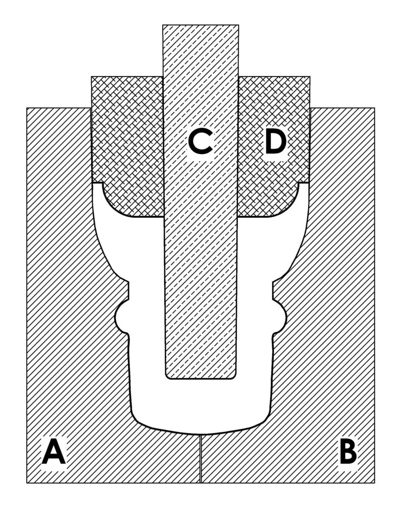
I hope I’ve not lost any readers at this point. This illustration shows the cross-section of the 734.8 style with the previously described measurements.
The part that caught my attention is that I can think of no other insulator where the variation in glass volume is seen in this manner. The common locations are the depth of pinhole {amount of dome glass} and length of the skirt, or a variation of this element.
Note: Underpoured and slumped insulators can also be illustrations of reduced glass volume, but are generally unique examples and were not considered for this topic.
To cast an insulator in such a manner, the mold tooling must also be slightly different than the tooling of the other insulator styles the hobby is familiar with.
All 734.8 examples have a mold line over the dome, indicating a two part mold was used to form the outer shape of the insulator. There is a fine mold line around the edge of the pin hole and another mold line around the outer edge of the base.
When considering these mold line locations and the variation in glass volume seen in these insulators, a unique method of insulator mold tooling must have been used.
The outer halves that formed the shape of the insulator would have had nearly parallel sides where the outer side of the skirt was formed. The examples I’ve measured show a very slight outwards taper near the base of the insulator, confirming this thought. A similar slight taper is also seen when measuring the pin hole diameters both at the top {dome} and where it exits to form the inner edge of the skirt. The taper is about .02” – .025”, enough to allow the pinhole mandrel to easily be withdrawn from the freshly formed insulator with little friction against the hot glass.
With the depth of the skirt being consistent, the pinhole plunger/mandrel would have been pressed into the molten glass, followed by an escutcheon-like piece {D} that followed the plunger and formed the insulator skirt in the glass that had been displaced upwards by the pinhole mandrel {C}. Mold part D of the tooling would also center the pinhole mandrel as it had very little tolerance to the sides of the main casting halves {A & B}. The center hole would have been very close to 1” in diameter and the outer diameter was 2.00”. As most aqua or olive 734.8 insulators are 2.08” – 2.12” across the base, this leaves .04”- .06” clearance from the edge of the skirt mold to the side of the main outer molds.
The pinhole mandrel was .97” – .98” in diameter at the tip, but soon became the 1.00” required to essentially seal around the hole in mold piece D, which formed the skirt of the insulator.
Somehow this skirt forming portion of the tooling {D} was matched with the pinhole mandrel {C}, yet was allowed to move up and down along it’s vertical axis. There would have had to be considerable pressure applied to this part {D} such that the skirt would be completely formed in the molten glass. Inserting the pinhole mandrel would not create much resistance as the glass could easily flow upwards around it.
To completely form the skirt, pressure would be required to force the hot air upwards around the outer edge of mold part D, probably leaving a glass hair-lip around the edge of the freshly formed insulator base. These 2 pieces {C & D} of the mold would have been matched, yet independent of each other. With the heat of molten glass happening, I don’t think a spring would have been able to keep the required pressure on the skirt mold {D} tooling. This piece must have been separately pressed as the last piece of the insulator casting process.
Every 738.4 base shard that has the actual flat surface of the insulator base, has chipping and/or a rough outer edge. This serves to illustrate the escape route of the hot air and gases from with-in the mold {parts A & B} as mold parts C & D were inserted into the molten glass. A fragile hair-lip of glass was probably in place at this time, but would generally have broken off as the tooling was removed from the freshly pressed insulator. Quite a few insulators have fine shards of glass stuck to the inner surface of the skirt. Other shards have similar small chips attached to the glass surface at the top of the pinhole.
These fine chips would have been stuck on the face of the tooling and remained there till the next insulator was pressed and they were then “grabbed” from the face of the tooling by the cooling glass of the next insulator. These bits could only stay in place with a base/plunger tool that was pressed into the molten glass and removed directly with no rotation.
There is no question of rotation at any point in the manufacturing of these insulators. I suspect they were manually pressed in these simple 4 piece molds. As the glass is of a crude quality, it leads to reason that the molds would also be simple but functional. It is not clear if/how the mandrel {C} and skirt forming piece {D} were connected, but like parts A and B they were closely matched.
As base pieces with taller skirts are studied, a more pronounced outer mold line and related roughness can be seen. Unfortunately I am only able to measure the base diameter on a dozen or so examples. These are enough to confirm that the skirt side forming portions of the main molds {A & B] were almost parallel though. The actual flat surface of the base is only about .13” wide and with the stresses of removing mold parts C & D, it is easy to see why so many of these insulators have roughness and chipping to the base and outer edge of the skirt. Also, most of these insulators had a rough ride over long distances by horse and wagon out to northern Saskatchewan. I expect there were a few chips in the bottom of the insulator barrels when they arrived on-site.
There are at least 3 different skirt radiuses that all lead to fragile base edges. With the fitting of the various coins it is easy to see that there is variation in the mold parts that formed the inner profile of these insulators. As there are several proven molds based on the exterior profiles, it stands to reason that there would variations in mold parts C & D also.
Credit and thanks for help with this column is given to Sergio Pari {illustrations} Dario Dimare {confirmations}, Don Briel {original illustration use} and Ren Settle/Mark Lauckner {Crown Jewels – Sept 1972, Mar & Apr 1997}
Good Collecting …….. Robin
Robin Plewes, McDonald’s Corners, Ontario.
For more Information on the Battleford Telegraph Line and it’s insulators please visit:
The Telegraphs of Western Canada at Historical Canadian Glass Plus